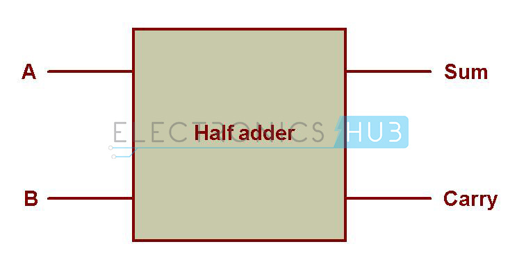

It is basically a 1-bit binary adder with 2-bit output. Now such circuit is called a half-adder circuit. THEORY: Half-Adder: A combinational logic circuit that performs the addition of two data bits, A and B, is called.
#Half adder truth table and circuit Patch#
COMPONENTS REQUIRED: IC 7400, IC 7408, IC 7486, and IC 7432, Patch cards and IC Trainer Kit.
#Half adder truth table and circuit full#
To design, realize and verify a full subtractor using two half subtractors. half adder half adder carry sum sum a carry b c x y 0 1 1 1. Question 4.12: (Solution, p 4) Fill in the truth table at right for the following circuit.

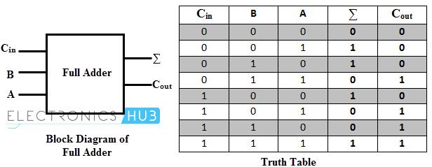
We also need two outputs from this circuit, 1-bit for the data-output and 1-bit for the carry-output. To design, realize and verify full adder using two half adders. Question 4.11: (Solution, p 4) Draw two truth tables illustrating the outputs of a half-adder, one table for the output and the other for the output. They are also used in other parts of the processor, where they are used to calculate addresses, table indices, increment and. In many computers and other kinds of processors adders are used in the arithmetic logic units (ALUs). This operation needs a circuit with 2 inputs (the least significant bit of the first operand and the least significant bit of the second operand). An adder is a digital circuit that performs addition of numbers. Half Adder Definition, Block Diagram, Truth Table, Circuit Diagram, Logic Diagram, Boolean Expression and Equation are discussed. In the previous example, the first operation is adding two 1-bit data of the least significant bits of two binary numbers. Half Adder is a combinational logic circuit used for the purpose of adding two single bit numbers. As we can see, every digit operation (except for the least significant bit) is made by adding the bit-data input, then add the carry-data from the previous digit operation, and passing the carry-output (if any) to the next digit operation. The next operation, the digit-2 operation will be similar with the digit-2 operation but the result of the addition is added by carry-output of the previous digit operation before placing the result in the corresponding digit position. The Boolean functions describing the half-adder are: S A B C A B. Addition will result in two output bits one of which is the sum bit, S, and the other is the carry bit, C. The result of this addition should be 10, but we have to place the least significan digit (0) in one digit of the result (the digit-2), so the most significant bit of the result (1) will be separated as the “carry” output of the digit-2 operation, designated as carry-1 in the picture. APPARATUS: THEORY: Half-Adder: A combinational logic circuit that performs the addition of two data bits, A and B, is called a half-adder. The next step is operating the digit-2 addition, and it shows 1+1. The operation on the input show the operation of 1 + 0, and the result is 1, and it fits in one digit place so there no “carry” of the digit-1 operation. To add two binary numbers 111 (7 in decimal) and 10 (3 in decimal), first we add the digit-1 (the least significant bit).


 0 kommentar(er)
